Experiments
The Tuapeka linear turbine has been investigated through controlled vane-cascade experiments and field tests in rivers, tidal flows, and flumes. These experiments have examined the relationship between theoretical predictions and measured vane forces, as well as practical operation for water pumping and electricity generation.
This page groups the experimental work by purpose and the quantities or behaviours investigated. For a chronological record of prototype development and field testing, see the Development page.
Experimental Vane-Cascade Tests
Model tests were carried out to investigate the behaviour of a balanced turbine vane and its relationship to the surrounding vane cascade. The test apparatus used a model vane mounted downstream of a cascade, with the inlet flow velocity measured using a flow meter.
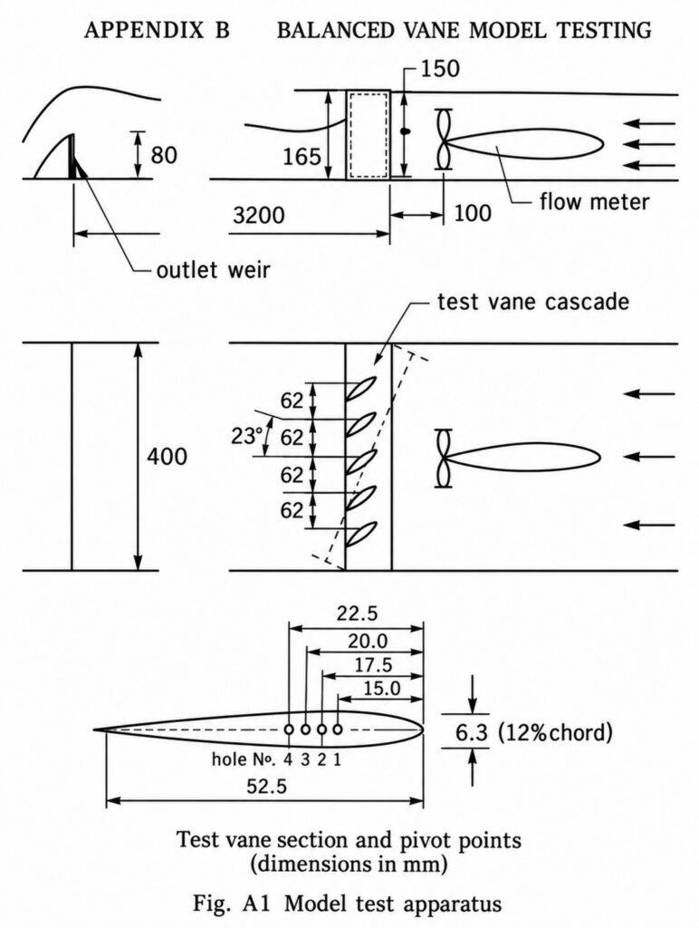
The tests examined the relationship between vane angle of attack and pivot position at inlet flow velocities of 0.4, 0.5 and 0.6 m/s. Additional measurements were made with the cascade turned through 23 degrees.
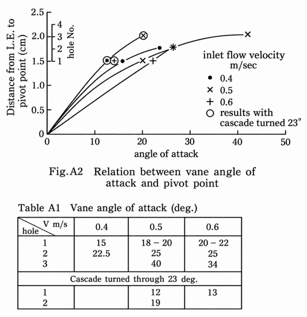
The results show how the equilibrium vane angle changes with pivot position and flow conditions. These experiments provided practical information for selecting the vane pivot position and for the balanced-vane design used in the turbine.
Water Pumping
Water pumping was one of the principal practical applications investigated during the development of the linear turbine. Tests ranged from early demonstrations in Japan and Thailand to later field trials of the mini linear turbine in New Zealand.
Early Pumping Tests — Japan and Thailand, 1984–1986
The 1984 tests in Fukui, Japan, included water pumping using the linear turbine in open-channel flow in the Kuzuryu River and an irrigation canal. The tests also demonstrated that the turbine could rotate in the same direction irrespective of the direction of water flow, a useful characteristic for tidal-flow applications.
Further tests were carried out in the Pai River in northern Thailand in 1986. The turbine was used to pump water up to a village while also demonstrating electricity generation for lighting.
Pai River, northern Thailand, 1986 — linear turbine test demonstrating water pumping and electricity generation.
14 March 2014 — Whakatane River, New Zealand
A later field test used the mini linear turbine to drive a water pump in the Whakatane River. The turbine was tested both suspended from a rail in the river bed and floating in the river. Bicycle derailleurs were used to support the upper chain between the end wheels and help prevent the chain from coming off.
The water pump was constructed from PVC pipe and fitted with two brass check valves.
Whakatane River, 14 March 2014 — mini linear turbine operating a water pump.
9 April 2014 — Rakaia River, Canterbury
At the Rakaia River, the mini linear turbine was tested while simultaneously pumping water and generating electricity for a small car tail-light bulb using a treadmill motor/generator.
Near the end of the test, the electrical load was disconnected. The turbine speed and pump flow rate then increased slightly as the load on the turbine was reduced.
Rakaia River, 9 April 2014 — simultaneous water pumping and electricity generation using the mini linear turbine.
14 April 2014 — Heathcote River, Christchurch
A series of tests in the Heathcote River investigated water pumping at different heads. The mini linear turbine was demonstrated pumping at a low head of approximately 1 metre and at higher heads of approximately 5–6 metres.
The tests also demonstrated the operation of the turbine vanes and simultaneous water pumping and electricity generation using a treadmill motor/generator. During one test, restricting the river flow immediately upstream of the vanes caused the turbine speed to decrease considerably.
Heathcote River, 14 April 2014 — comparison of water pumping at approximately 1 metre and 6 metres head.
Heathcote River, 14 April 2014 — simultaneous water pumping and electricity generation; turbine speed decreases when the upstream flow is restricted.
Electricity Generation
Electricity generation was tested using several generator and transmission arrangements. The field experiments included a twin-alternator system driven through a chain-and-belt step-up transmission and, later, a smaller treadmill motor/generator used with the mini linear turbine.
17 January 2013 — Orewa River
A tidal-flow test at the Orewa River used two 500-watt automotive alternators for electricity generation. A chain-and-belt step-up drive increased the rotational speed to approximately 2,000 rpm.
A water pump was fitted to the opposite end of the turbine and operated through a crank drive. The pump was made from PVC pipe and used two glass balls as check valves.
Orewa River, 17 January 2013 — tidal-flow test with two 500-watt alternators and a crank-driven water pump.
7 April 2014 — Heathcote River, Christchurch
The mini linear turbine was subsequently tested with a treadmill motor/generator. A bicycle-wheel step-up chain drive transmitted power from the turbine to the generator, which was connected to a car tail light.
Heathcote River, 7 April 2014 — treadmill motor/generator and car tail light driven through a bicycle-wheel step-up transmission.
A separate close-up test measured an electrical output of 5 volts while the treadmill motor/generator was powering the car tail light.
Voltage measurement during the Heathcote River test — 5 V while powering a car tail light.
Tidal and Reversing Flow
One characteristic investigated during the development of the linear turbine was its ability to operate where the direction of water flow changes. Because the vanes can change their operating angle, the turbine was tested for its behaviour in reversing and tidal flows.
Fukui, Japan — 1984
Open-channel tests in the Kuzuryu River and an irrigation canal demonstrated that the linear turbine could continue to rotate in the same direction irrespective of the direction of water flow. This characteristic suggested a potential application in tidal currents, where the flow reverses periodically.
Fukui, Japan, 1984 — open-channel testing, including water pumping and demonstration of same-direction turbine rotation with reversing flow.
Orewa River, New Zealand — 2013
The reversing-flow concept was later tested directly in a tidal current at the Orewa River on 17 January 2013. The turbine was equipped with two 500-watt automotive alternators driven through a chain-and-belt step-up transmission, with a crank-driven water pump fitted at the opposite end.
The Orewa test video is shown in the Electricity Generation section above.
Flow and Vane Behaviour
Field testing also provided observations of how the turbine vanes responded to non-uniform river flow. These tests were less controlled than the model experiments described above, but they helped identify practical operating behaviour under real river conditions.
13 April 2014 — Heathcote River
During a test in the Heathcote River, the turbine drove a generator and powered a light bulb with the water pump disconnected. Some of the vanes were observed not to set correctly. The original test record suggested uneven river flow as a possible cause.
Heathcote River, 13 April 2014 — generator test showing the operation of the vanes; uneven river flow was considered a possible cause of some vanes not setting correctly.
14 April 2014 — Effect of Upstream Flow Restriction
A test on the following day provided a simple demonstration of the turbine’s sensitivity to the flow reaching the vanes. While the turbine was pumping water and driving a treadmill motor/generator to power a car tail light, the photographer stood in the river immediately upstream of the turbine and partially blocked the flow. The turbine speed decreased considerably.
The video demonstrating this effect is shown in the Water Pumping section above.
Measurements and Flume Testing
In addition to the field demonstrations, measurements were made during several tests to provide quantitative information about turbine operation. These included electrical-output measurements and later testing in a flume where the water-flow speed could be measured.
Electrical Measurement — 7 April 2014
During the Heathcote River test, the treadmill motor/generator produced a measured output of 5 volts while powering a car tail light. The test and voltage measurement are documented in the Electricity Generation section above.
Flume Test — 29 March 2016
A later test on 29 March 2016 placed the linear turbine in a flume. The test included water pumping and measurement of the water-flow speed, providing a more controlled test environment than the earlier river trials.
Flume test, 29 March 2016 — linear turbine test including water pumping and flow-speed measurement.
Experimental Record
The experiments documented here range from controlled model testing to practical trials in rivers, tidal currents and a flume. They record both successful demonstrations and operating observations that informed the continuing development of the Tuapeka linear turbine.
The Development page provides the chronological history of the prototypes and field tests, while the Publications page contains the technical papers describing the theory and design in greater detail.