Design
A Simple River Flow Linear Turbine Design for Developing Countries
(Paper presented at the Winter Annual Meeting of the American Society of Mechanical Engineers, Anaheim, December 7-12, 1986. Fourth International Symposium on Hydro Power Fluid Machinery)
TABLE OF CONTENTS
ABSTRACT
INTRODUCTION
DESIGN PARAMETERS
THEORETICAL ANALYSIS
DESIGN
INSTALLATION AND TESTING
CONCLUSIONS
ACKNOWLEDGEMENTS
REFERENCES
COMPUTER PROGRAM
BALANCED VANE MODEL TESTING
DRAWINGS
ABSTRACT
There is a need in developing countries for a simple inexpensive means of harnessing the seasonal low head energy flow of rivers. The linear turbine which consists of a cascade of vanes moving in a horizontal loop across the river flow, is ideally suited to this application since, due to low flow loadings and simple design, it can be constructed from locally available material and by local manpower.
A small size (1Kw) linear turbine design is developed as a useful prime mover for household power etc. and as a means to develop the skill and experience to build larger units. To design this turbine a computer analysis of the flow conditions is made and several possible configurations are discussed.
The final design uses two loops of chain to support sheet metal vanes which are balanced so that the vane angle can change to suit operating conditions and the vanes can be tripped for speed control. Power take off is by means of a modified bicycle transmission and “v” belt drive to two car alternators. The whole assembly is supported in the river by floats and cables to the river bank.
In developing countries where energy is a basic requirement for development there is an urgent need to harness the vast source of energy that is flowing away daily in rivers and canals. The most common types of water flow energy conversion systems use rotating turbines due to their low maintenance and operating costs. This justifies the high initial cost of design and manufacture including building dams. However the needs for developing countries are vastly different. As well as the need to develop the natural energy resources of rivers etc. there is also a great need to develop the large source of human talent that is lying idle.
A number of systems have been proposed to meet this need. The system being developed by the Intermediate Technology Development Group (1) is one. This uses a four bladed Darrieus turbine mounted either horizontally or vertically in the river flow below the surface. Construction is very simple and a unit built by local labour is now operating on the White Nile in Southern Sudan.
The Salford oscillator(2) being developed by Wilson, Bassett and Jones at Salford University is also a possible system. This is a linear system and hence its size is not limited. It consists of a barrage of vertical vanes that oscillate back and forth across the flow. Presently a tidal power unit is being developed.
The Schneider engine(3) is another alternative. It is also a linear system, however, in its present configuration with horizontal vanes it requires a dam. Also since the vane angles are fixed it requires guide vanes which add to the cost and complexity.
The linear turbine system proposed by Ishida and Service (4) offers the most promise to meet the needs of developing countries. It is similar in layout to the Schneider engine but with the vanes in a horizontal loop instead of vertical loop. Its main difference is that the vanes can swing to take up the optimum angle to the flow and this does away with the need for inlet guide vanes. To date there has been little work done on developing this system and it is the purpose of this paper to develop a feasible design which can be made by interested persons and groups throughout the world, and so develop the necessary operating experience to build larger and more suitable designs to meet their own needs.

Fig.1 Power available from a 600mm deep flow as a function of flow velocity.
To satisfy the above requirements a small size unit seems most appropriate as this will be simpler and cheaper, however it must be big enough to be useful.
With this in mind the following design parameters were chosen:
1. Approximately one kilowatt capacity from a river flow of 1m/sec.
2. Simple and cheap construction from locally available materials by semi—skilled labour using simple tools.
3. Portable for ease of maintenance and site changing to meet seasonal demands.
4. Simple to operate and versatile.
To meet these design parameters a vane depth of 600mm was chosen since this would result in a compact portable unit and also enable optimum use of sheet steel or plywood which comes in 1800mm (6 foot)length sheets. To determine the required length of the turbine a design analysis using this vane size is made.
THEORETICAL ANALYSIS
The theory of Ishida and Service (4) can be used as a guide to determine the length and operating conditions of the turbine. A summary of this theory is given in the form of a computer program in appendix A. The theory is based upon open channel flow conditions where the linear turbine completely blocks the flow. This is the ideal case but will not be practical in most situations due to river size, river navigation and seasonal changes in river flow.
For open channel flow the energy available to the turbine is dependent upon the difference between the flow energy upstream and the minimum energy required to maintain the volume flow rate. This can be expressed as (5):
where q is the flow per unit width of upstream flow and g is the gravitational constant.
Fig.2 Theoretical power output and loads for a 0.8m/sec 600mm deep upstream flow.
X- force on vanes transverse to flow
Y- force on vanes in direction of flow
Fig.3 Relative inlet and outlet angles for a vane speed of 0.9m/sec.
The energy available is therefore:
For a fixed vane depth (h), equation (2)shows that the energy available is a function of inlet velocity (C). This function has been calculated by the program in appendix A and is plotted in Fig.1. It shows that the maximum energy available for 600mm inlet flow is 0.96 Kw/meter at a flow velocity of 0.8 m/sec.
At higher flow velocities and hence volume flow rates the energy available decreases down to zero as the upstream flow conditions become critical.
For 600mm deep vanes therefore, the optimum flow will be 0.8m/sec. Hence this value is used in the computer program (appendix A) to determine the theoretical operating conditions. A plot of the results is given in Fig.2 which shows a maximum power output of 0.89 Kw/meter occurring at a vane speed of 0.9m/sec. The flow inlet and outlet angles for this vane speed are given in Fig.3. and this shows that to achieve the theoretical power output of 0.89 Kw/m requires a stage 1 flow deflection of 11 deg.(59.4—48.4) and a stage 2 flow deflection of 39.2 deg. (38.8+0.4). Just how close these conditions can be approached will depend upon the design of the vanes, vane spacing and actual flow conditions.
According to the theory, for an ideal flow of 0.8m/sec with 600mm deep vanes, 0.89Kw power output can be obtained per meter of span. For an initial design analysis therefore a 2 meter wide turbine with 600mm deep vanes will be considered with the hope of obtaining 1Kw power output.
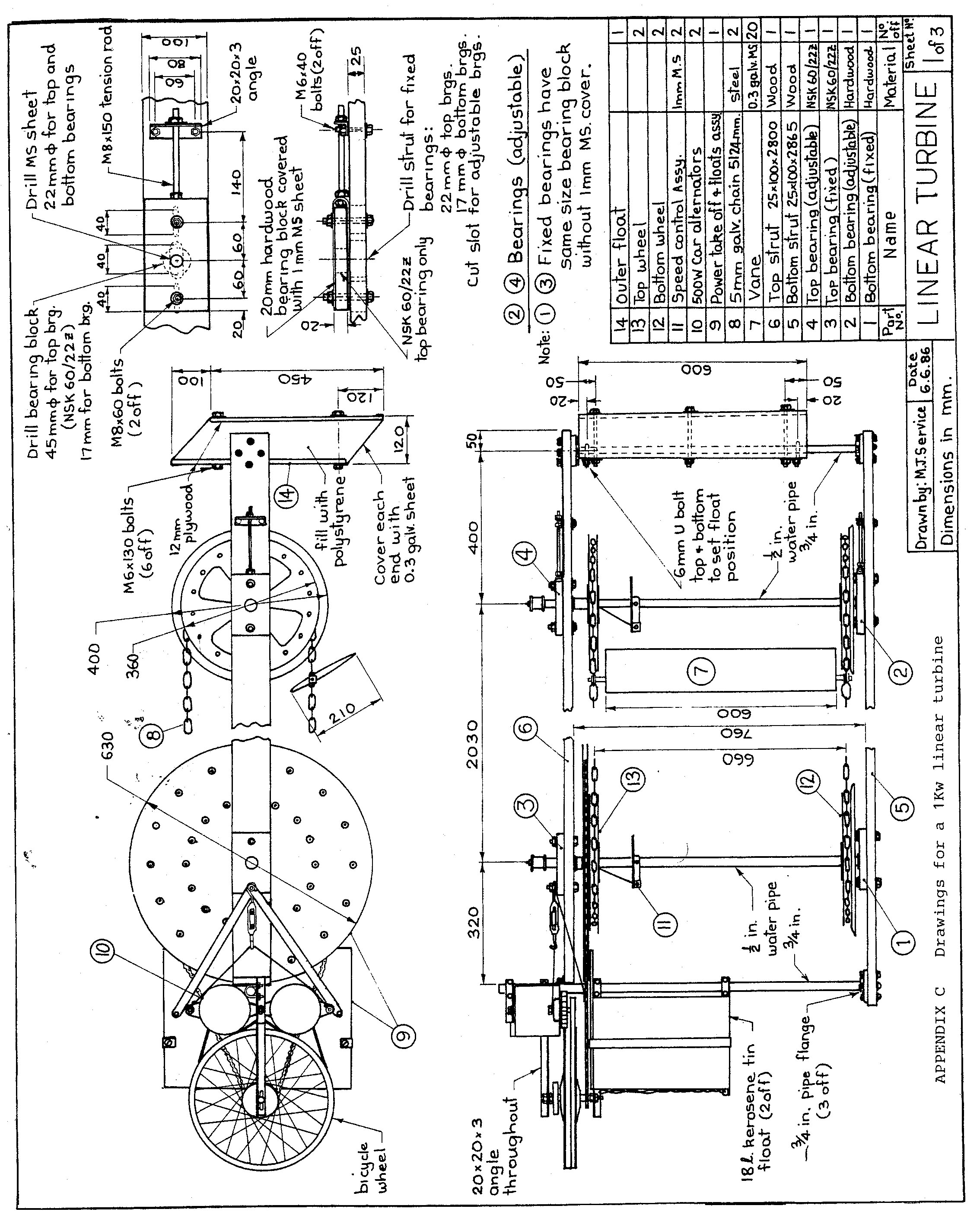
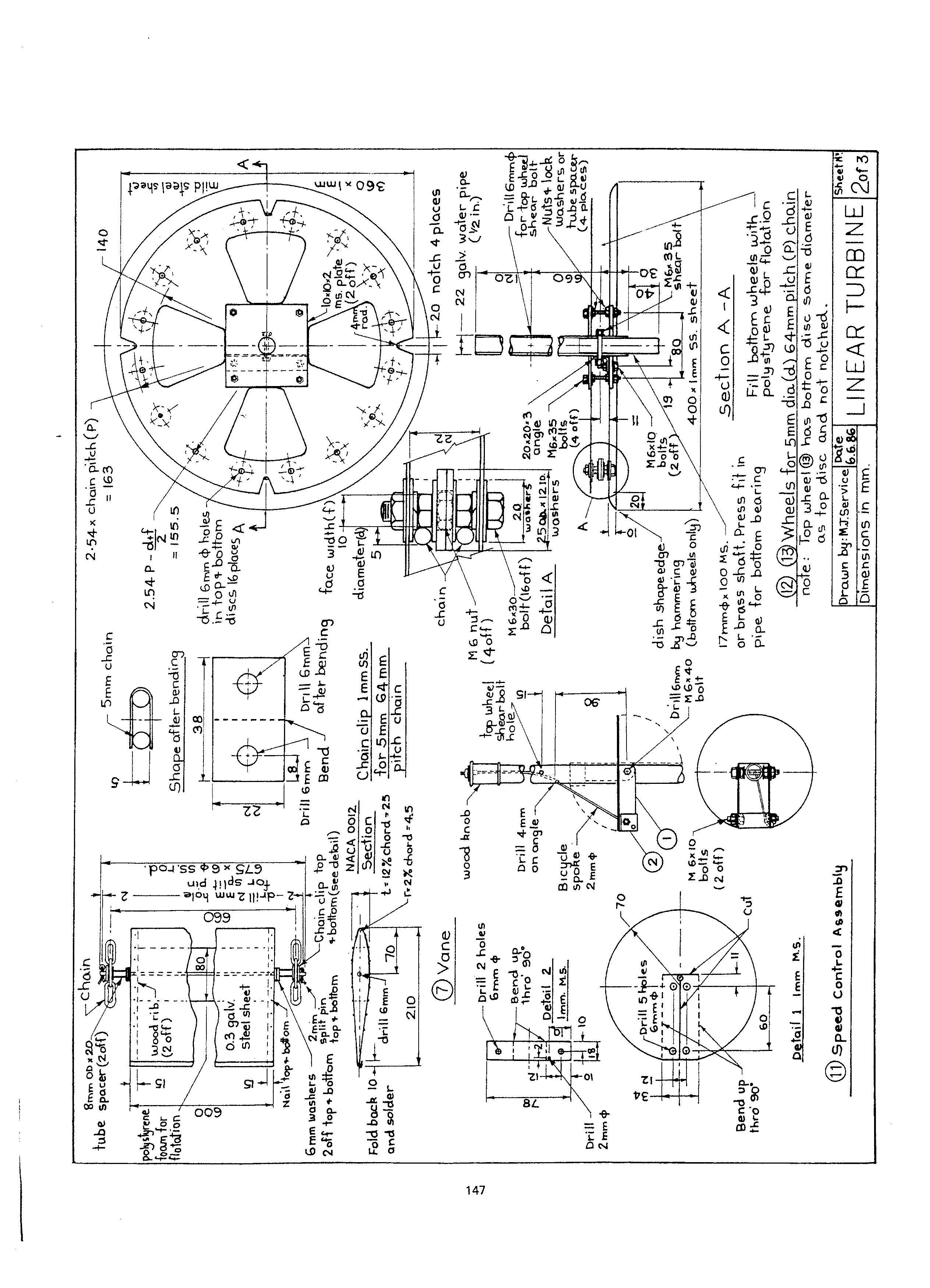
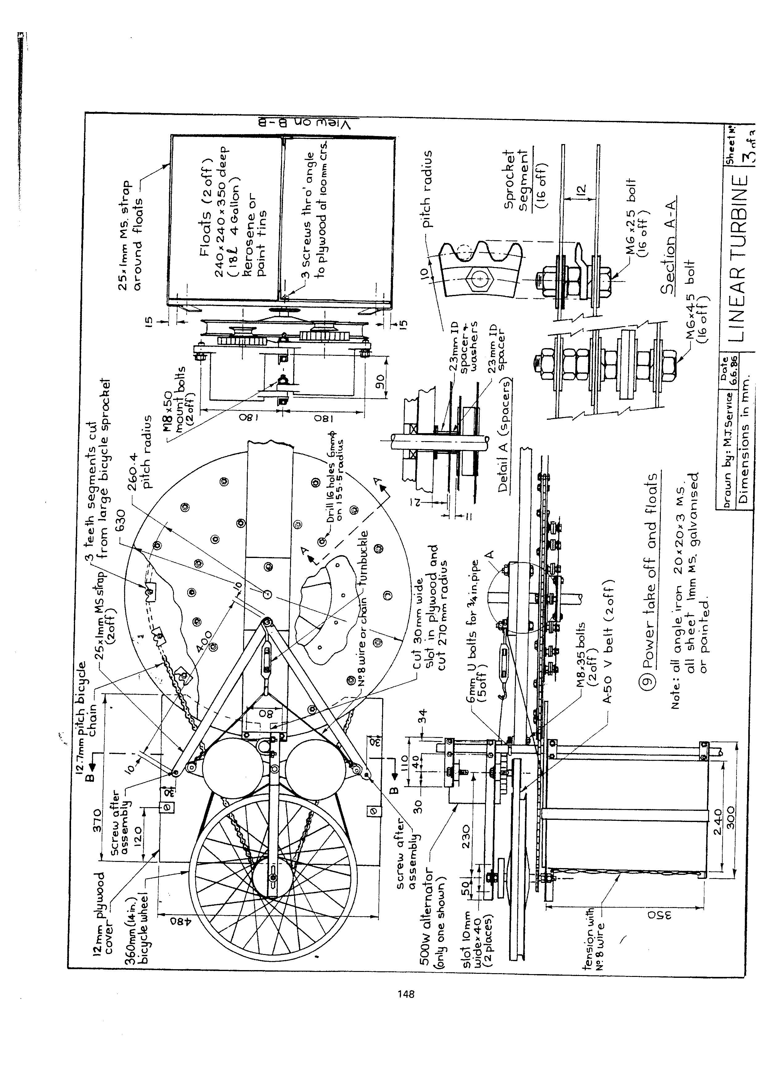
One arrangement using ropes/cables to support the vanes is shown in Fig. 4 and full working drawings for one possible design using chain to support the vanes are given in appendix C.
The vanes can be either curved or symmetrical. However, by choosing symmetrical vanes a balanced vane system can be used eliminating the need to set the vane angles (see balanced vanes)
To determine the optimum design the various options need to be considered in the light of the design parameters.
Vane Support and Drive
The type of vane support depends upon locally available materials and tools. Possible systems are rope, cable or chain.
Rope/cable system. With the rope or cable vane support system shown in Fig.4, simple wheels (i.e. bicycle wheel rims) can be used, making a cheap, lightweight design. The main problem with this system however is that since the top and bottom loop lengths cannot be made identical due to stretch, the top and bottom wheels must be able to rotate independent of each other so that the vanes remain vertical as they move across the flow. Thus either a method of bracing is needed at various intervals along the cascade as in Fig. 4 (a), or the vane attachment to the cable must provide a resistance to skewing as shown in Fig. 4(b).
With either method however the drive from the top and bottom wheels must be independent, necessitating either 2 separate power outputs, or a single power take—off through a differential system. Due to these problems it is felt that a chain system will be more satisfactory.
Chain system. The chain system uses standard galvanized chain and has the advantage that the top and bottom loops can be made the same length. Thus the top and bottom wheels can be fixed to the same axle resulting in a direct drive from both loops to the power take—off. Also having chain links makes vane attachment at the correct spacing a simple matter. The main disadvantage with chain is that simple bicycle wheel rims are not suitable since it is difficult to locate the chain positively on the rim and match the rim diameter to the pitch circle diameter (PCD) required for the chain. Therefore special sprocket wheels must be made to suit the chain pitch. A possible design is shown in Fig. 5.
This design can be made cheaply using simple tools, and the PCD can be increased by drilling new holes to accommodate chain stretch when overhauling. Washers are used as teeth with the size chosen to suit the chain “eye” size. If suitable washers are not available triangular teeth can be cut from mild steel and drilled to take the place of washers.
There are various methods to attach the wheel to the axle. Perhaps the simplest is by welding. However if a welder is not available the axle can be drilled and the wheel bolted to the axle using an angle iron bracket (see appendix C).
Lightening holes are cut in the wheels to reduce weight and the bottom wheels can be filled with polystyrene to provide flotation if needed.
The bottom disks of the two bottom wheels are made larger in diameter and dished to guide the chain on to the sprocket, while the inner disks of the top and bottom wheels are notched to accommodate the vane support shafts. Wheel size is dependent upon chain pitch and the number of teeth. Reducing the number of teeth results in a smaller wheel and simplifies construction, however the velocity fluctuation of the chain will increase. For a 16 teeth wheel the velocity fluctuation is given by Hinkle(6) as 2% and this increases to 3% for a 12 teeth wheel.
Increasing the number of teeth results in a larger wheel with smoother transmission, however the rotational speed will be less for a given chain speed, requiring a greater step up gear ratio to the power take-off. As a compromise a 16 teeth wheel is chosen.
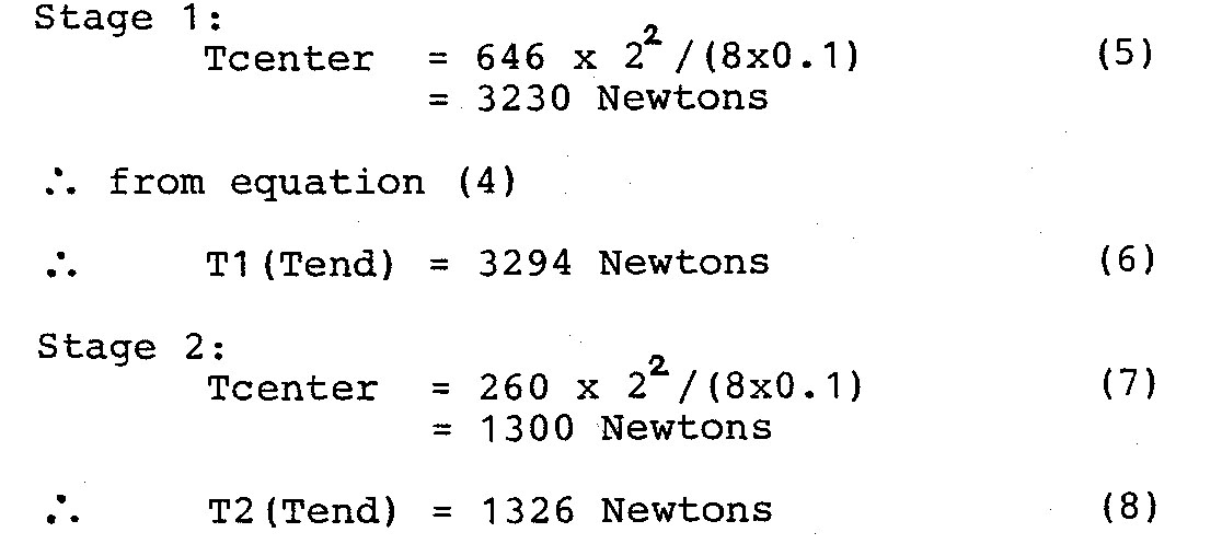
The loads on the chain due to the hydraulic forces on the vanes are represented in Fig.6. Theoretical values for X1,X2,Y1,Y2, are shown by the curves in Fig.2. At zero vane speed the X loads are high, however these values are for theoretical flow deflections of well above 40 deg. In practice with symmetrical (not curved) vanes, flow deflections greater than 40deg. will not be possible. At maximum power condition (vane speed 0.9m/sec) the maximum theoretical stage 2 flow deflection decreases to 39.2 deg. which is a more realistic value, and so chain loads at this condition will be considered for the initial design. From Fig.2 the values of X1, X2, Yl, Y2, are 435, 551, 646, 260 N/m respectively. To determine the loads on the chain due to these loads, the catenary loads are calculated from the formula(7):
where: T is the tension
W is the span width
Y is the load per meter
y is the deflection from a straight line
Assuming a 0.10m deflection over a span of 2 meters, the catenary load is:
Max. load = 2X1 + 2X2 + Ti + T2 (9)
= (435+ 551)x2 + 3294+ 1326
= 6592 Newtons
Thus for two chains (top and bottom) with 5mm dia. links, the total cross sectional area is:
For 5mm mild steel chain the tensile strength is approx. 30 kg/mm2. Therefore:
Safety factor = 30/8.6 = 3.5 (12)
For an initial design this safety factor seems adequate.
Vanes
Vane size. For a balanced vane system, to enable control of the turbine speed (see Speed Control), the vane trailing edge must clear the main axle. Thus, for a typical 5mm chain with a pitch of 64mm, the pitch circle radius for a 16 teeth wheel for this chain will be (from Fig.5) 2.54 x 64 = 163mm. Therefore, the vane support must be no more than 152mm from the trailing edge, for the vane to clear the axle (22mm dia.). For balanced vanes the support is at the 1/3 chord position so the chord can therefore be no greater than 228mm. Thus a vane size of 210mm is considered for the initial design with 20 vanes spaced at 256mm giving a maximum width between the centers of the wheels of 2050mm (zero chain deflection).
Materials. Vanes can be made from various materials such as canvas, plywood, sheet steel etc. Three possible types of vane are shown in Fig. 7.
Canvas vanes (a) require a frame and are not as durable as wood or sheet steel but have the advantage of light weight and the ability to curve to a streamline shape at either angle of attack.
Plywood vanes (b) are the simplest and probably the cheapest to make. With a vane size of 600mm by 210mm, two 1800mm by 900mm sheets of plywood are sufficient to make 24 vanes. However plywood vanes require painting to seal the surface to prevent delamination. Also a flat shape vane is not as efficient as a streamline shape.
Sheet steel vanes(c) can also be made simply, by bending the sheet around wooden aerofoil shaped ribs. If the steel is galvanized it does not need painting and it can be easily joined by soldering. Foam can be fitted inside to provide flotation.
Attachment methods. Four attachment methods are shown in Fig.7.
The attachment method in (a) has the bearing bolt fixed to the vane so that rotation is at the chain link. With the attachment method in (b) however for attachment to a rope/cable, this is not possible since rotation would wear the rope/cable. With this method a bearing bracket must be used attached to the vane. If a stiffer attach method is needed (i.e. if bracing shown in Fig.4(a)is not used) then the bottom attach method of (b) with steel plates can be used.
The attach method in (c) for the sheet metal vanes uses a single shaft which passes through the vane. This method gives minimum disturbance to the flow and enables the vanes to be fitted and removed from the top end, simplifying maintenance and site installation. In the case of a large turbine, this feature is essential, as the unit must first be positioned across the flow before the vanes can be fitted. The bearing shaft can be either secured by a locked nut as shown at the top or by a split pin as shown at the bottom. The nut method requires tapping the shaft, while the pin method requires drilling, which may not always be possible depending on available tools.
Balanced Vanes
For optimum performance the vane angles must be set at the optimum angle to the flow. The theory (4) predicts that this optimum angle is dependent on flow conditions and vane speed.
Values for the optimum vane angles for a 0.8m/sec flow were given in Fig. 3. The angles could be set by the use of links or ties attached to the vane, however for different operating conditions (flow velocity and vane speed) the angles must be changed to maintain optimum performance. This requires calculation of the flow angles for the different conditions and resetting the vane angles; an exercise that may not always be possible with semi—skilled personnel. Hence a balanced vane system is considered to be more suitable.
The simple balanced vane system depends on the lifting characteristics of a symmetrical airfoil. Namely, the center of pressure moves back with increase in angle of attack. Consequently choosing a pivot point behind the center of pressure for zero angle of attack (1/4 chord) results in the airfoil angle of attack increasing until the center of pressure coincides with the pivot point. This principle has been used in the Flap Wing (8) and is used in balanced control surfaces on aircraft and balanced rudders on ships etc.
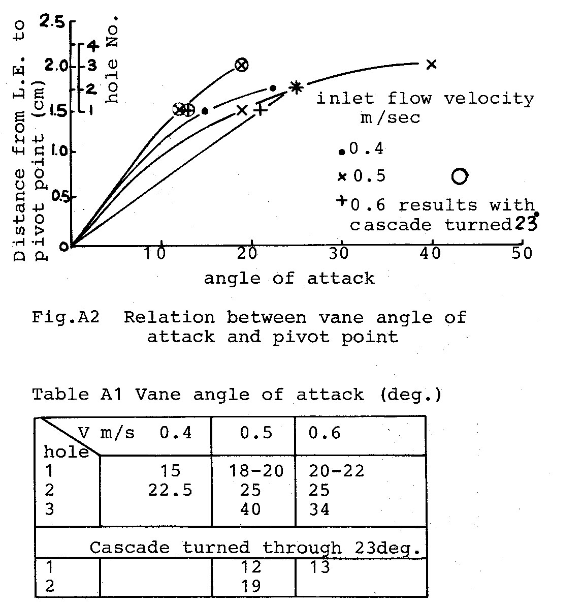
To determine the pivot point for various angles of attack, model tests were carried out (see appendix B). Results of these tests are given in Fig. 8. Although the tests were only a preliminary investigation, the following trend was observed for a given pivot point.
1. Increase in flow velocity gives an increase in flow turning angle.
2. Increase in the angle of the cascade to the flow gives a reduction in flow turning angle.
From the theoretically optimum values of Fig. 3, for a flow of 0.8m/sec, the required stage 1 and stage 2 flow deflection angles are 11 degrees and 39.2 degrees respectively. The stage 1 inlet angle is 48.4 deg. and the stage 2 inlet angle 0.4 deg., and equivalent model flow velocities approx. 0.6 m/sec. (V model = 1/2 full size velocity).
From Fig.8, for a stage 2 flow deflection angle of 39deg., the vane should be pivoted at 38% chord. Unfortunately no tests were made with the cascade at 48 deg. to represent the stage 1 conditions, however, extrapolation of the results suggests that a pivot point of approximately 33% chord would give the desired 11 deg. deflection with a 48 deg. inlet angle. From these tests, a pivot point of 1/3 chord was considered for the initial design.
Speed Control
With the balanced vane there are two stable conditions as shown in Fig.9. One position will produce a driving force and the other a braking force to the chain. To set the vane in the driving position the angle of attack must be greater than the relative flow inlet angle as the vane leaves the end wheel. This can be achieved by tripping the trailing edge with a pivoted plate attached to the main axle as shown on the right axle in Fig.9. If this plate is turned through 90 deg. as shown on the left axle, it will only trip every second vane as it passes around the wheel so that half the vanes will be at the braking angle, causing the turbine to slow down and stop. Speed control and stopping can thus be achieved by means of these control plates fitted to the axles at each end. Starting the turbine requires turning by hand until sufficient vanes are at the driving angle to continue the motion automatically.
Power Take-off
Since a cheap simple system is required, two 500 watt car generators were chosen to produce an output of 1Kw. The voltage output from these generators is only 12 volts (or 2×12=24v). To obtain a higher voltage the generators can be modified by taking 12v AC direct from the stator winding before the rectifier and transforming this to a higher voltage. Alternatively a battery and inverter system can be used.
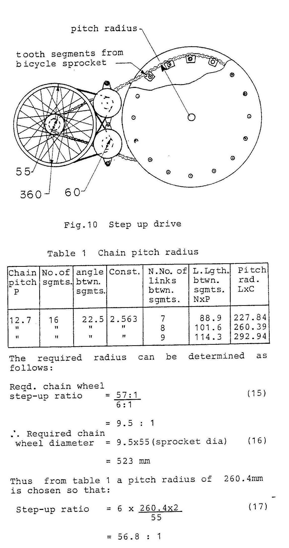
Since the normal operating speed of a car alternator is from 2000 —4000 rpm. a step—up drive from the turbine is needed. The required step up ratio can be determined as follows:
= 52.7
Thus for a 3000rpm alternator drive:
Reqd. step—up ratio = 3000 /52.7 (14)
= 57 : 1
A simple step—up drive system using a bicycle chain and bicycle wheel as a pulley is shown in Fig. 10. This system can be made cheaply from spare parts and is light in weight. To prevent the “V” belts from slipping on the bicycle wheel rim a rubber ring cut from a car tyre inner tube can be stretched around the inside of the rim. The bicycle wheel is a standard 36Omm(14 inch) wheel with a 55mm dia sprocket and when connected to a standard 60mm diameter alternator pulley gives a 6:1 step-up ratio. Additional step-up is obtained by the large chain wheel which is made up of 3 tooth segments from two large bicycle sprockets. These are positioned at a pitch circle radius to match the chain pitch.
Table 1 can be used to calculate a suitable radius which is dependent on the chain pitch and number of links between segments.
Bearings
Bearings are needed to support the wheel axles. Since the lower bearings are under water, journal bearings are used. These can be made of brass, high density plastic, teflon or hardwood such as teak soaked in oil. For the present design, hardwood is chosen as the cheapest and simplest bearing.
The upper bearings could also be journal bearings like the lower bearings. However, if the turbine is designed with the axles extending through the bearings to provide an additional power take—off, then ball bearings are more suitable. To protect the ball bearings from the weather and spray, sealed bearings should be used.
Floats
For shallow rivers the whole unit can either rest on the bottom or be supported with legs to the bottom. However, for deeper rivers or rivers with fluctuating water levels a float support system is more satisfactory.
The design shown in the drawings in appendix C has pipes at each end for rigidity and float attachment. Various types of float such as bamboo rafts, logs, boats etc. can be attached depending on what is available. The present design has 18 litre kerosene tins attached to the power take—off end with a simple polystyrene filled float supporting the light end. Additional tins can be attached and partially filled with water to give the correct vane depth depending on the weight of the generators and other equipment that might be used such as batteries, pumps, inverters etc. The level of the light end can be adjusted by raising or lowering the float position on the support pipe.
Installation
The unit is designed so as to be easily disassembled for transportation and installation. If the vanes are removed to reduce weight and minimize flow resistance, it can be installed by one man and the vanes fitted after installation.
For optimum performance the unit needs to be positioned in a channel flow of approximately 0.8 m/sec. For small rivers it may be possible to create this condition by filling in the sides of the river and/or building a weir. However for large slow flowing rivers where this is not possible the unit should be positioned in the fastest flowing section of the river.
A single attach point method shown in Fig.11(a) may be adequate. This has the advantage in that with large floating debris the support ropes deflect it away from the vanes and the unit can swing in towards the river bank. However to position the unit more centrally in the faster flow, it may be necessary to have a rope fixed to points on each bank, and the unit attached by pulleys to enable it to be retrieved, as shown in (b)
Testing
The linear turbine in the configuration shown in the drawings (appendix C) has not yet been tested. However in the process of developing this final design a number of prototypes have been tested. It is felt that the present design satisfies the original design parameters and all that remains is to determine the power output. If on testing, the planned power output of 1Kw is not achieved, it is a relatively simple matter to extend the length of the turbine and add more vanes until 1Kw power output is obtained.
The final design satisfies the design parameters of a simple, cheap, portable linear turbine for rivers of approximately 0.1m/sec flow. Field testing of this turbine in rivers throughout the world is required to gain operating experience and so develop the design to suit local needs.
Hopefully, interested groups and individuals will build and test this design so that useful experience can be gained. The author would welcome any enquiries and suggestions and offers his services to coordinate the development of linear turbines.
The author would like to thank Professor Otani, Head of the Department of Engineering of Fukui Institute of Technology, for permission to use the Departments facilities, and Messrs. T. Mori and K. Hasegawa, graduate students, for their assistance in making and testing the various prototypes.
1. Garman,P. ”Development of a Turbine for Tapping River Current Energy”, Appropriate Technology, Vol.8, No. 2, September 1981, pp.10—13.
2. Wilson, E.M., Bassett,D.E.,Jones,I.D.,”Two New Machines for Hydraulic Power from Low Heads,” 12th IAHR. Symposium, Stirling, 27—30th August 1984, paper 5.5,pp.535—548.
3. Schneider Engine Co., Lift Translator power production,( Rt. 1, Box 81, Justin, Texas 76247, USA.
4. Ishida,K. and Service,M.J. “Theoretical Conditions Related to an Open Channel Flow Linear Turbine”, ASME Small Hydropower Fluid Machinery ,1984 pp.101—106.
5. Schaum’s Outline Series, Fluid Mechanics and Hydraulics, McGraw—Hill, 1977.
6. Hinkle,R.T., Kinematics of Machines, Second Edition, Fig.10.13, Maruzen, Tokyo.
7. Timoshenko and Young, Engineering Mechanics, Fourth Ed., McGraw—Hill, 1956.
8. Gerharz,R. “The Flapwing, a Unique Fluid Machine Element”, ASME Transactions, Journal of Fluids Engineering, Vol.100, June 1978, pp.237—238.
Computer program for theoretical analysis
The following program is for a Sharp PC-140I or similar pocket computer and is based on the theory of Ishida and Service(ref.4). Their paper should be consulted for more detailed nomenclature and derivation of equations.

VISUAL BASIC CODE FOR THE SAME PROGRAM
Function JS()
Dim B(2) As Double, C(2) As Double, H(2) As Double, V(2) As Double, P(4) As Double, D(2) As Double
Dim A(2) As Double, Q As Double, U As Double, W As Double, Z As Double
Dim E As Double, K As Double, X As Double, M As Double, T As Double, J As Double, Y As Double, ZZ As Double
Dim S As Double, G As Double, Dd As Integer, TX As Double

S = 0
G = 9.81
C(1) = 1.3
A(1) = 0
H(1) = 0.8

Q = C(1) * Cos(A(1)) * H(1)
H(0) = (Q ^ 2 / G) ^ (1 / 3)
P(3) = 3 * H(0) / 2
P(4) = C(1) ^ 2 / (2 * G) + H(1)
P(0) = 1000 * Q * G * (P(4) - P(3))
Debug.Print "POWER AVAILABLE="; P(0)
V(0) = (G * H(1)) ^ (1 / 2)
If V(0) < C(1) Then Debug.Print "SUPERCRIT FLOW=": Exit Function

U = InputBox("U=")

P(1) = 0
W = 0
Z = 0
TT = 0.384
B(1) = Atn(TT)
D(1) = B(1) * 57.29577951

Line45:

B(1) = Atn(((C(1) * Sin(A(1)) - U) / (C(1) * Cos(A(1)))))
D(1) = B(1) * 57.29577951
V(1) = C(1) * Cos(A(1)) / Cos(B(1))
E = 1 / (2 * G) * V(1) ^ 2 + H(1)
H(0) = 2 / 3 * E
V(0) = (G * H(0)) ^ 0.5
B(0) = -ArcCos(Q / (V(0) * H(0)))
D(0) = B(0) * 57.29577951

Line101:
Debug.Print "INLET ANGLE=" & D(1)
'Print USING("#####.##", D(1))
Debug.Print "CRIT OUTLET ANGLE=" & D(0)
': Print USING("#####.##", D(0))
Debug.Print "CRITICAL FLOW ?"

Dd = MsgBox("Critical Flow?", vbYesNo, "JS")
'INPUT "Y/N ";D$

If Dd = vbNo Then GoTo Line130

Debug.Print "Critical Flow"
B(2) = B(0)
H(2) = H(0)
V(2) = V(0)
GoTo Line270

Line130:
D(2) = InputBox("OUTLET ANGLE?")
Debug.Print "OUTLET angle B2=" & D(2)
B(2) = D(2) / 57.29577951
If Abs(B(2)) < Abs(B(0)) Then GoTo Line138
Debug.Print "ANGLE TOO BIG": GoTo Line130

Line138:
If Abs(B(2)) > Abs(B(1)) Then GoTo Line140

Debug.Print "ANGLE TOO SMALL": GoTo Line130

Line140:
K = (Q / Cos(B(2))) ^ 2 / (2 * G)
X = H(1)

Line160:
M = X ^ 3 - E * X ^ 2 + K
T = 3 * X ^ 2 - 2 * E * X
J = X - M / T
If J < 0 Then Debug.Print "ERROR"
ZZ = Abs((J - X) / X)
If ZZ < 0.000001 Then GoTo Line250
X = J
GoTo Line160

Line250:
H(2) = J
V(2) = Q / (H(2) * Cos(B(2)))

Line270:
A(2) = Atn(((V(2) * Sin(B(2)) + U) / (V(2) * Cos(B(2)))))
C(2) = V(2) * Cos(B(2)) / Cos(A(2))
Debug.Print "OUTLET DEPTH=" & H(2)
P(0) = 1000 * Q * U * (V(1) * Sin(B(1)) - V(2) * Sin(B(2))) ' was P
Debug.Print "POWER/METER=" & P(0)
X = 1000 * Q * (V(1) * Sin(B(1)) - V(2) * Sin(B(2)))
Y = 1000 * Q * (V(1) * Cos(B(1)) - V(2) * Cos(B(2))) + 1000 * G * (H(1) ^ 2 - H(2) ^ 2) / 2
Debug.Print "FORCE X/M=" & X
Debug.Print "FORCE Y/M="; Y
P(1) = P(1) + P(0) 'was P
W = W + X
Z = Z + Y
S = S + 1
Debug.Print "STAGE 2"
If S > 1 Then GoTo Line380
C(1) = C(2)
A(1) = -A(2)
H(1) = H(2)

GoTo Line45

Line380:
Debug.Print "TOTAL POWER W/M=" & P(1)
Debug.Print "TOTAL FORCE X/M=" & W
Debug.Print "TOTAL FORCE Y/M=" & Z

End Function

Function ArcSin(X As Double) As Double
ArcSin = Atn(X / Sqr(-X * X + 1))
End Function

Function ArcCos(X As Double) As Double
ArcCos = Atn(-X / Sqr(-X * X + 1)) + 2 * Atn(1)
End Function

Sub clean()

End Sub
NOMENCLATURE
A = flow angle to direction normal to chain
B = relative flow angle
C = flow velocity
E = specific energy
H = flow depth
P = power per meter
Q = flow per unit width
U = vane speed
V = relative flow velocity
X = force in direction of chain
Y = force perpendicular to chain
(0) = critical conditions
(1) = inlet conditions
(2) = outlet conditions
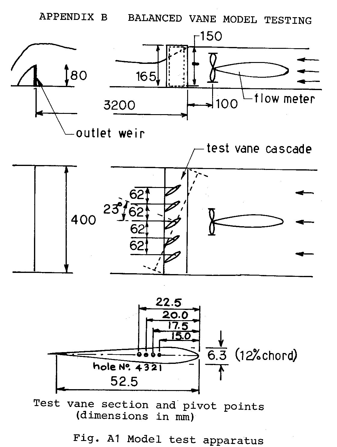
Tests were made to determine the relation between the pivot position and the angle of attack of the vane.
The apparatus of Fig. A1 was used. Flow velocity was measured with a propellor type flow meter. One quarter scale vanes were made up of 0.2mm steel sheet and folded to a NACAOO12 section with the trailing edge soldered. Four 1.2mm bearing holes were drilled in plates soldered to each end. The vanes were held in position at 62mm spacing by 1mm rods passing through the vanes and into a 4mm plastic sheet frame at top and bottom. The trailing edge of the vanes were connected by a tie rod to damp the oscillations.
Flow Velocities.
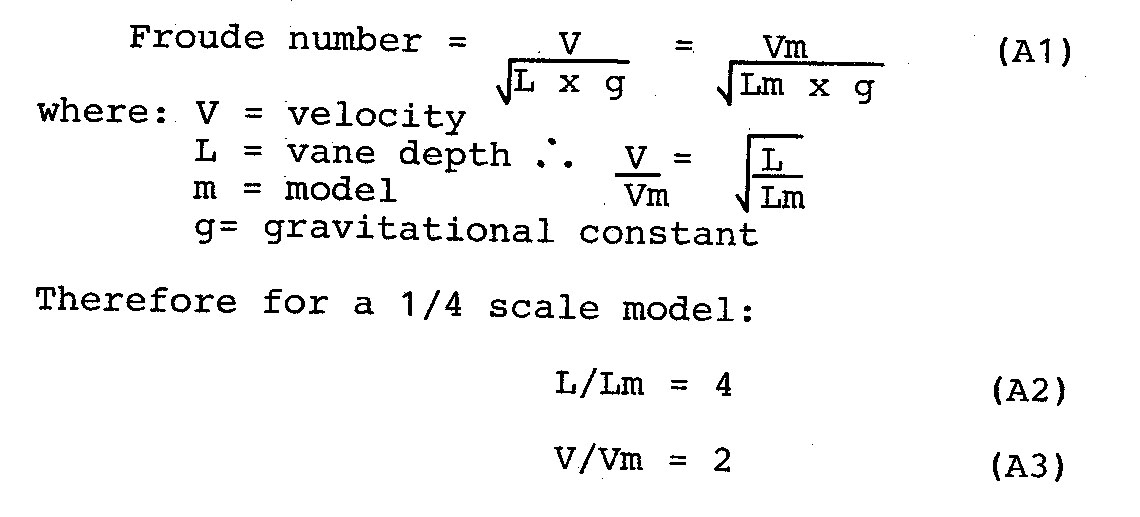
Since the controlling factor is Froude number, the velocity ratio was determined as follows:
Therefore tests were made with velocities ranging from 0.4 to 0.6 m/sec representing actual flow velocities of 0.8 to 1.2 n/sec.
Results are given in Table Al and plotted in Fig. A2. Due to the small size of the apparatus accuracy was not very good. Flow velocities were accurate to ± 0.05 m/sec and the flow depth ranged from 120 to 140 mm.
Further tests are needed, preferably with full size vanes in a channel flow, to obtain more accurate data for design.
DRAWINGS
APPENDIX C Drawings for a 1 Kw linear turbine





Recent Comments